Flagship project · Individual dissertation
Designing a lighter Formula Student suspension upright
A simulation-led design study balancing mass, modelled structural margin, vehicle fit, manufacturability, cost, and environmental impact for a Formula Student electric car.
From chassis to upright.
Formula Student · Design visualisation
The whole system.
Start with the chassis. Every connection has a role.
A silent design visualisation moves from the full vehicle chassis to the front wheel, hub and upright, separating the assembly to show its components.
Compare the designs
The lightest option has a cost.
Simulation & cost estimates · April 2025
Iteration 5 keeps most of the weight saving without Iteration 6’s larger machining bill. Compare the geometry, structural results and estimated cost together.
All three designs stay side by side. Scroll the table to compare on smaller screens.
Starting geometryBaseline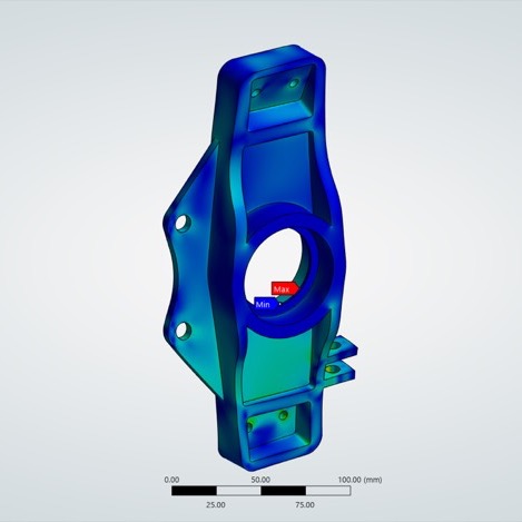 | RecommendedIteration 5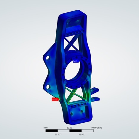 | Lightest designIteration 6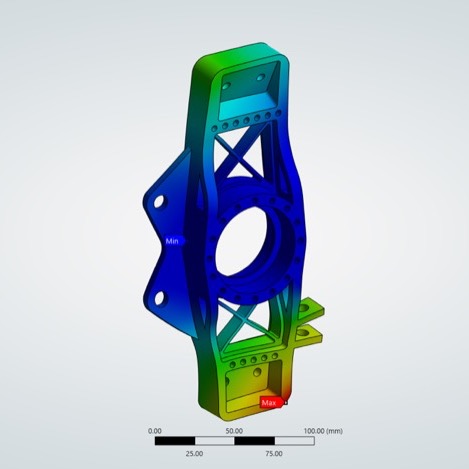 | |
|---|---|---|---|
| Mass | 0.67248 kg | 0.54852 kg | 0.53793 kg |
| Max. deformation | 0.06215 mm | 0.08923 mm | 0.11245 mm |
| Safety factorThreshold ≥ 2.0 | 13.51 | 4.80 | 4.72 |
| Est. machining | £69.53 | £75.53 | £110.29 |
Why Iteration 5
Iteration 6 saves another 10.59 g, but costs £34.76 more (+46.0%) to machine and increases maximum modelled deformation by 26.0%. Both exceed the model’s 2.0 safety-factor threshold; Iteration 5 is the recommended practical balance.
ANSYS stress images use individual colour scales; compare geometry visually and numerical results in the table. These are simulations, with no physical, fatigue or track validation. Machining estimates include machine and technician time with VAT; stock, carriage, inspection, assembly and testing are excluded.
See all six iterations and the method01 · Overview
The objective was optimisation—not simply weight reduction.
The upright connects the wheel hub to the suspension links and brake assembly. Reducing its mass can lower unsprung weight and improve vehicle response, but indiscriminate material removal can weaken load paths, increase deformation, and make the component more difficult or expensive to machine.
The study therefore asked how far the supplied baseline geometry could be redesigned while remaining structurally credible under the modelled load cases, compatible with the surrounding vehicle, and practical for low-volume manufacture.
Why not headline the lightest version? Iteration 6 was the final and lightest simulated geometry at a 20.01% mass reduction. The additional 10.59 g saving beyond Iteration 5 came at a materially higher estimated machining cost, so Iteration 5 remained the recommended practical option.
02 · Scope
A constrained component inside a larger system.
Design constraints
- Maintain a minimum modelled factor of safety of 2.0.
- Preserve the supplied wheel, bearing, brake, wishbone, and pushrod interfaces.
- Withstand combined vertical, braking, and cornering load cases.
- Remain feasible for low-volume manufacture within a Formula Student budget.
My contribution and boundary
I developed the load calculations, material screen, CAD redesigns, mesh-convergence study, finite-element analyses, iteration logic, and manufacturing-cost comparison.
Queen Mary Formula Student supplied the baseline vehicle geometry and key vehicle parameters. The project did not include physical manufacture, fatigue testing, or track validation.
03 · Load model
From vehicle assumptions to component loads.
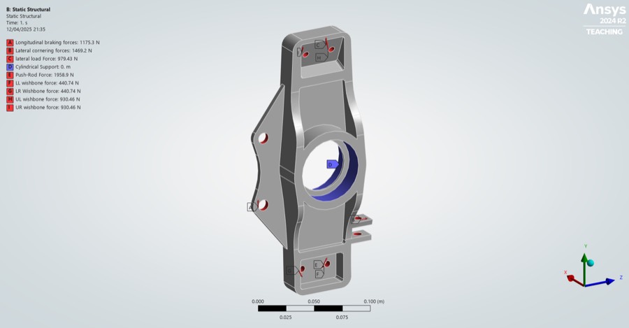
I translated vehicle-level assumptions into forces at the upright's interfaces, then applied those forces as boundary conditions in ANSYS. The inputs represent design assumptions and supplied parameters—not measured track telemetry.
04 · Material selection
Material choice was treated as a multi-variable decision.
The screening process considered specific stiffness, yield strength, fatigue-strength data, fracture toughness, machinability, cost, and environmental impact. Aluminium 7075-T6 narrowly led the weighted decision matrix because it offered the strongest overall balance for a highly loaded, low-volume component.
Scroll the table horizontally to see all columns.
| Candidate | Weighted score | Decision |
|---|---|---|
| Aluminium 7075-T6 | 4.45 | Selected balance of strength, mass, and manufacturability |
| Titanium Ti-6Al-4V | 4.36 | Strong performance; cost and machining weighed against it |
| Aluminium 6061-T6 | 2.94 | More accessible, but lower strength for the application |
| Magnesium EA55RS-T4 | 2.73 | Low density; weaker overall feasibility score |
| Nickel-Cu-Si M-25S | 2.17 | Lowest overall fit among the shortlisted candidates |
The report presents the overall scores but does not reproduce the detailed weighting calculation. Treat this as a project-specific screening exercise—not an independently reproducible or universal material ranking.
05 · Numerical convergence
Check mesh sensitivity before optimising the geometry.
Six meshes ranged from 14,078 to 1,138,160 elements. Stress and deformation began to stabilise above approximately 400,000 elements, so the later design iterations used a 0.75 mm mesh with 729,174 elements.
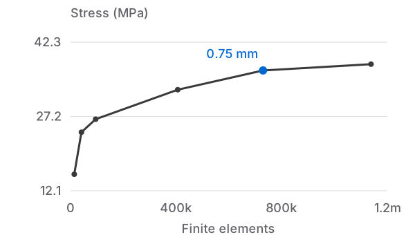
View chart data
| Mesh (mm) | Finite elements | Stress (MPa) |
|---|---|---|
| 5 | 14,078 | 15.43 |
| 3 | 41,231 | 23.99 |
| 2 | 95,058 | 26.636 |
| 1 | 405,987 | 32.634 |
| 0.75 — selected | 729,174 | 36.554 |
| 0.6 | 1,138,160 | 37.83 |
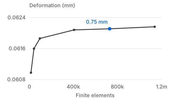
View chart data
| Mesh (mm) | Finite elements | Deformation (mm) |
|---|---|---|
| 5 | 14,078 | 0.060978 |
| 3 | 41,231 | 0.061617 |
| 2 | 95,058 | 0.061888 |
| 1 | 405,987 | 0.062116 |
| 0.75 — selected | 729,174 | 0.062145 |
| 0.6 | 1,138,160 | 0.062199 |
Under the modelled load case, the baseline geometry returned 36.55 MPa maximum von Mises stress, 0.06215 mm maximum deformation, and a factor of safety of 13.51.
06 · Design development
Six iterations—and one useful failure.
The geometry developed through controlled material removal, an over-aggressive failed concept, structural reinforcement, and local refinement. Iteration 3 reduced mass most aggressively but broke the safety requirement, forcing the next design to restore clearer load paths through truss-like reinforcement. Iteration 6 was the final and lightest simulated output; Iteration 5 was the recommended practical cost-performance option.
FOS 13.511
10.692
2.263
1.294
5.235
4.806
4.72
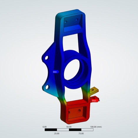
Scroll the table horizontally to see all columns.
| Version | Mass | Reduction | Deformation | Stress | FOS | Outcome |
|---|---|---|---|---|---|---|
| Baseline | 0.67248 kg | — | 0.06215 mm | 36.55 MPa | 13.51 | Reference |
| Iteration 1 | 0.64117 kg | 4.66% | 0.07511 mm | 46.19 MPa | 10.69 | Pass |
| Iteration 2 | 0.54458 kg | 19.02% | 0.23164 mm | 218.18 MPa | 2.26 | Pass, limited margin |
| Iteration 3 | 0.53378 kg | 20.63% | 0.33576 mm | 381.55 MPa | 1.29 | Rejected |
| Iteration 4 | 0.58479 kg | 13.04% | 0.11140 mm | 94.37 MPa | 5.23 | Reinforced |
| Iteration 5 | 0.54852 kg | 18.43% | 0.08923 mm | 102.92 MPa | 4.80 | Recommended |
| Iteration 6 | 0.53793 kg | 20.01% | 0.11245 mm | 104.54 MPa | 4.72 | Final / lightest |
07 · Manufacturing
Performance had to remain practical to produce.
Casting, forging, additive manufacture, and CNC machining were compared. CNC machining was selected because it suited the required tolerances, the 7075-T6 analytical material, and low-volume production. Iteration 6 was estimated to require more setup, machining distance, and technician time, producing a substantially higher cost estimate.
These figures combine estimated machine and technician time, including VAT. They exclude separately quoted raw stock, carriage, inspection, assembly, testing, and validation. The analytical model used 7075-T6 properties, while the supplier quote referenced AW7075-T651 stock; that temper distinction would need to be reconciled before manufacture.
08 · Recommendation
The lightest design was not the strongest decision.
Iteration 6 reduced modelled mass by 20.01%, but saved only another 10.59 g relative to Iteration 5. That incremental saving increased estimated machining cost by £34.76—approximately 46%—while modelled deformation rose from 0.08923 mm to 0.11245 mm.
Iteration 5 therefore offered the more defensible cost-performance balance: an 18.43% modelled mass reduction, a factor of safety of 4.80, lower deformation than Iteration 6, and substantially lower estimated machining cost.
Decisions and lessons · Individual dissertation
Make the marginal trade-off visible.
- My contribution
- I connected the load calculations, material selection, CAD iterations, mesh study and manufacturing estimates into one design comparison.
- Decision
- I recommended Iteration 5 because the extra 10.59 g saved by Iteration 6 came with higher deformation and a £34.76 increase in estimated machining cost.
- Lesson
- A stable simulation supports a comparison under the chosen assumptions. Physical validation needs separate evidence, particularly for repeated loads and the real suspension assembly.
- Next check
- Fatigue analysis and prototype bench testing would test the design beyond its static finite-element results. These remain proposed work.
09 · Evidence boundary
What the work demonstrates—and what remains unproven.
Demonstrated in the study
- Translation of a system-level problem into component loads and constraints.
- Numerical sensitivity checking before geometry optimisation.
- Rejection of an unsafe iteration rather than defending the lightest result.
- A clear recommendation balancing mass, safety, deformation, and cost.
Not established by the study
- No physical prototype, bench test, assembly test, or track validation.
- Loads relied on supplied and assumed inputs because measured telemetry was unavailable.
- No component fatigue analysis or material testing.
- Directional manufacturing and environmental estimates rather than full production economics or LCA.
The results on this page are finite-element outputs under the stated load and boundary-condition assumptions. They are evidence of the engineering and decision process—not certification of a competition-ready component.